Improving data product accuracy using GCPs during the image capture process.
How to use Ground Control Points (GCPs)
Improving data product accuracy using GCPs during the image capture process.
Accuracy of maps and other data products depends on the accuracy of the geotags on the images captured during a mapping flight and on the ability of the mapping engine to position the map accurately on the earth's surface. A common way to improve the accuracy of maps and other data products is to place ground control points (GCPs) around the area of interest, to be photographed during the image capture process. GCPs have known GPS positions, which provide a "hook" the processing engine can use to more accurately position the final data product.
Measure Ground Control (MGC) supports manual marking only of GCPs via its mapping product workflow integration with Pix4D. To make the marking process as simple as possible, we recommend one of three types of GCP targets: square, diagonal, and Aeropoints. These GCP targets should have a clearly defined center, and be at least 2 ft x 2 ft (60 cm x 60 cm) in size.
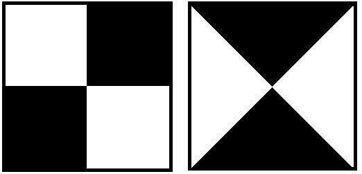
Example Ground Control Point Patterns
For most accurate results, pilots should:
- Operate drones equipped with Real Time Kinematics (RTK) systems that connect to a base station and use a data corrections service (e.g. NTRIP/CORS). You can also correct data post flight with PPK (Post Processing Kinematics).
- When choosing GCPs be aware that some have built-in positioning systems and others require the use of additional survey equipment to accurately geolocate. A high accuracy GPS device should be used to capture coordinates and elevation for each GCP.
- If you don't have a separate GPS device you can use your drone to collect the GCP coordinates. Take a picture sitting on top of each GCP and later extract the coordinates and elevation from each GCP image's EXIF data. The backup method described, especially with elevation is much less precise, but has proven to improve model results when compared to not using GCPs. Be careful to avoid damage to your sensor when sitting atop a flexible GCP in uneven terrain.
To use GCPs in making new data products and maps:
- Note: GCPs are only available for Pro/Enterprise accounts. Please upgrade your individual account to Pro or contact support@measure.com if you are interested in an Enterprise trial in order to use GCPs.
- Ensure that the imagery captured is nadir (ground facing) imagery. Oblique imagery may result in less accuracy when processing and may be more difficult to mark.
- Place GCPs and record their coordinates within the operational area prior to conducting a flight. Use 5-10 GCPs for each site.
- Be sure to evenly distribute the GCPs throughout the site (do not cluster them in one part). Do not place GCPs on the corners or edges of the mapping area as they will only be visible in a small selection of photos and will be difficult for Pix4D to use when processing.
- Avoid placing GCPs too close to trees/other overhanging objects to ensure they are not obstructed during image capture.
- GCPs must be placed at a distance of at least 10 m/33 ft from each other.
- Refer to the GCP manufacturer's instructions for additional info on recording the coordinates of the GCP. Some use cases, such as mapping an elongated corridor, would require a modified GCP placement.
Example GCP Placement (Source: Pix4D)- Record the following information about each GCP:
If you need to convert your planar coordinates or MSL/orthometric heights for inputting your GCPs/converting your outputted data, please click this support article.
- Planar coordinates: (X/Y) coordinates, or the Longitude/Latitude in decimal degrees).
- Elevation: Measured relative to MSL using EGM 96 Geoid (feet/meters).
- Horizontal and Vertical accuracy: Margin of error (± feet/meters) as reported by the positioning device.
- Flights should be flown in nadir, oblique imagery may be harder to mark and produce less accurate results. Fly the site as normal, and upload the images to the MGC Web Portal.
- After uploading the dataset and selecting a processing template and ouput, the option to add GCPs will be available in Step 5 (Preview). Add the the relevant GCP information captured by your GPS device via the CSV upload button (coming soon) in the bottom left corner or click here to see how to add GCPs one-by-one manually. MGC supports up to 10 GCPs per data product; a minimum of 3 GCPs is required, and a minimum of 5 GCPs is recommended for good results.
- Coordinate position values must be specified in either a Projected Coordinate System (PCS), such as a state plane, or the World Geodetic System 1984 (WGS84) (EPSG: 4326) in decimal degrees.
- A positive latitude indicates a value north of the equator, and a negative latitude indicates a value south of the equator.
- A positive longitude indicates a value east of the prime meridian, and a negative longitude indicates a value west of the prime meridian.
- The Coordinate system specified must be a horizontal coordinate system. Vertical coordinate systems are unsupported.
- If WGS84 (EPSG: 4326) is selected as the coordinate system for your GCPs, the output coordinate system for your data will be in the corresponding UTM zone.
- Anywhere in MGC where feet/inch data can be entered or displayed is in accordance with the international foot/inch, and not a survey foot/inch. Please convert your survey feet/inch data to international feet/inch data if necessary for accuracy concerns.
- To properly capture elevation and accuracy parameters, please follow instructions and best practice supplied with the positioning device you’ve used to capture GCPs.
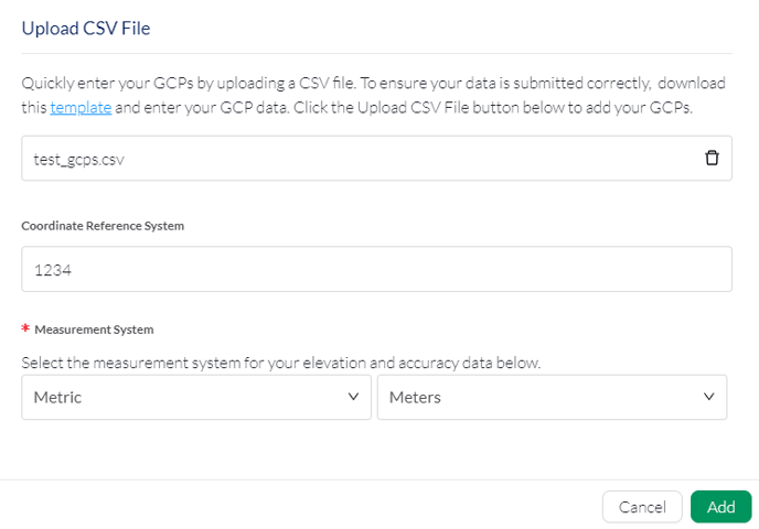
- If adding your GCP information via CSV (or alternatively fill in GCPs manually via these instructions), click on the CSV upload button, and download the template file to ensure your CSV column headers and data are organized correctly. Then upload the file, enter the coordinate system used in your GCP data (if not lat/long), and then the measurement system for your elevation and accuracy data:
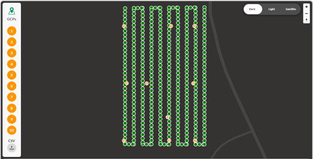
- Once you've added your file and relevant information, the Add button should turn green, meaning your GCPs are ready to be added to the map. Click add and the map will be updated:
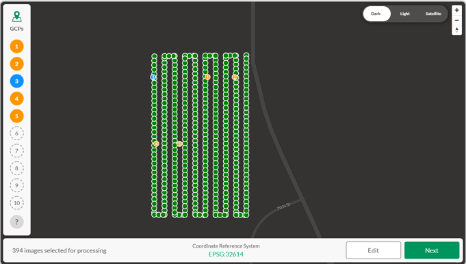
- GCPs that are orange in color have been added but have not yet been marked. Once a GCP has been marked, it will turn blue. When you're ready to mark a GCP, go ahead and click on a GCP on the map to open the the GCP marking tool:
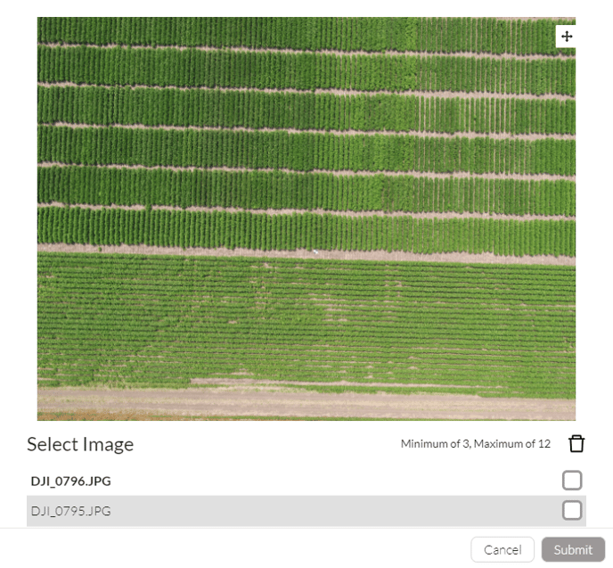
- The images in the list will automatically be sorted by the image center from nearest to farthest from the GCP. From here, pan and zoom the image, and click on the location with the image contains the GCP. The closer that you zoom in, the more precisely you can mark the GCP, leading to the most accurate results when processing.
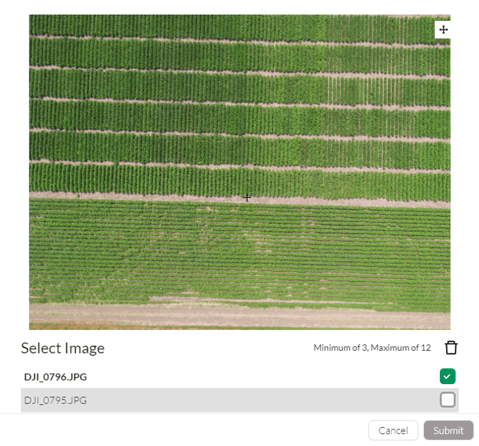
- When you have accurately located the center of the GCP, click on it to add a crosshair to the map:
- From here, continue working through the list to add more marks for the GCP. at least 3 are required, and 5 are recommended. Once you've added a sufficient amount of GCPs the submit button will turn green. Click on the submit button, and the GCP will turn blue to indicate it has been marked:
- Continue the marking procedure until all GCPs have been marked and click next and then submit the processing request as normal
If subsequent attempts to process maps with GCPs are unsuccessful or model results aren’t improved with GCPs, please contact support@measure.com for assistance.
- Note: Currently, MGC does not have the ability to process Checkpoints, only Ground Control Points. We can assist with processing Checkpoints for Pro and Enterprise Customers.
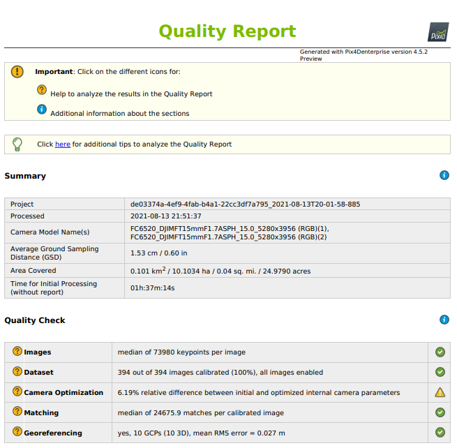
- Once data products are completed, you will receive a Quality Report via email. To verify that your GCPs have been detected and used, see the “Georeferencing” section of the report:
- If your GCPs were not properly incorporated check the following:
- Do the source images show the GCPs clearly visible in source imagery? Avoid high wind and flying too fast for your camera to function properly and save data between capture commands.
- Are there are several images for each GCP?
- Does the drone or sensor need recalibrated? Does the drone have proper satellite coverage, over 7, while flying?
- Double check the GCP coordinates, elevation and accuracy entries provided from your GPS device.

Related Articles:
Have questions or feedback? Please contact support.groundcontrol@ageagle.com